At present, several suitcases with automatic following function were on the market, which are mostly realized by vision or UWB technology. This article introduces how to use the BLE AoA direction finding technology to develop a car with automatic following function. The car can follow the beacon forward, turn around or stop.
Note: This article and reference code are only concept demonstration, and the paring of beacon and car is not considered.
Architecture
The following components are needed:
|
Items |
function |
|
ING9188xx 4x4 URA antenna array |
CTE collection and control |
|
Raspberry Pi Zero |
AoA calculation |
|
Car |
Including frame, motor and steering |
|
TB6612 Motor drive module (with 3.3V output) |
Drive the motor,and supply the antenna array |
|
DC-DC module |
Supply 5V for Raspberry Pi and Steering |
|
128x64 OLED(SSD1306) |
Display |
|
Li battery |
Power |
|
DuPont lines |
|
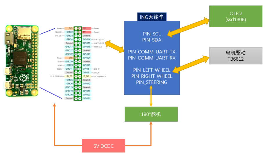
The block diagram of the car is shown below. The main controller is ING9188xx on the 4x4 URA, which submits the collected CTE data to Raspberry Pie to complete the azimuth calculation, and then adjusts the trolley's forward direction accordingly. In addition, an ING9188xx development board is needed to send CTE beacons (Peripheral LEC&CTE example code) to guide the trolley forward. The OLED module can be used to display debugging or status information. For its driver and usage, refer to Central Throughput example. Since the raspberry pie and the steering gear on the chassis require 5V power supply and consume a lot of power, DC-DC module is used to provide 5V output.

Details of main functions
1. Chassis Control
Due to the limited data rate of the IO port of the antenna array, the car can only move forward, not backward. For TB6612, motor drive, steering gear control, etc., please refer to the Bluetooth remote control vehicle.
Q: Raspberry pie has rich IO and powerful functions. Why not use it as the master?
A: We always tend to use our own products
2. CTE collection
AoX algorithm has a very large time and space complexity and cannot be run on a low power SoC such as ING918x. In fact, even for Raspberry Pie's low-end model Raspberry Pi Zero, 4x4 full array computing is still very difficult. Considering that we only need azimuth, we can only use 1 × 4 For ULA sub array, it takes about 0.1s for Pi Zero to complete a calculation.
In terms of implementation, the CTE is collected by example Central CTE in the way of extended broadcast, and then sent to raspberry pie for azimuth calculation after Base64 encoding.
3. Raspberry Pi control
The controller logs in to Raspberry Pie through the UART and starts the direction finding algorithm program alg_array_1x4. The next task is to send the Base64 encoded CTE data to Raspberry Pie, and then parse the JSON format solution results.
When implementing, consider:
1. Raspberry pie takes a long time to start. When logging in to the shell, fill in the user name and password;
2. When parsing JSON results, the algorithm program may report an error (status!='ok ');
3. The main control program is re executed (debugging and updating programs), and the raspberry pie is already in the login state (it is too inefficient to restart the raspberry pie), so it needs to be judged.
The above situations may lead to confusion of related codes.
4. Steering control
The car steering is controlled with PID:
• Error: (current azimuth minus target value)
• Controlled: steering gear angle
We set KiKi para to 00, i.e. use PP/DD to control.
5. Speed Control
The basic principle is that when the car is far from the beacon, the speed is faster, and vice versa. But according to the poor effect of RSSI range estimation, we jointly used a Kalman filter and an IIR filter to try to improve the accuracy of range estimation.
6. Stop Control
Safety first, in order to 1) prevent the car from hitting our feet, 2) realize the "emergency stop" function, use the hysteresis comparator to achieve a separate stop control logic in addition to speed control: once the (original) RSSI value exceeds a certain threshold (RSSI_LOCK), stop immediately, and stop other speed control logic; When the (original) RSSI is lower than another threshold, stop is released and other speed control logic is allowed to control the car movement.
Testing
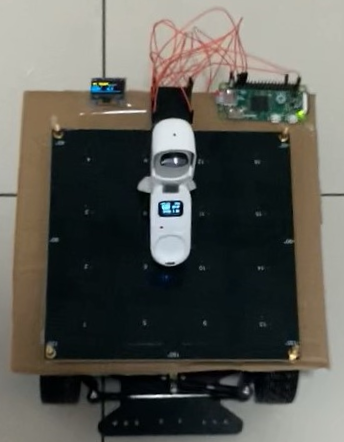
Refer to pin_def.h and the architecture to build the hardware as shownin the diagram, which added a Insta360 GO2(ING9187 inside) camera to record the video:

The software for different components:
|
Module |
Software |
|
ING9188xx 4x4 URA antenna array |
The app in this article |
|
Raspberry Pi Zero |
Raspberry Pi OS 及 alg |
|
ING9188xx EVB |
Peripheral LEC & CTE |
FOTA function is attached to the source code. After the initial burning, it can be easily upgraded through OTA. It is recommended to adjust REF_RSSi according to actual device (i.e. the signal strength received by the car 1m away from the beacon) to improve the effect of speed control and parking control.


